 网络设备配置
# 网络设备配置
# 15. 网络设备配置
# 15.1. 网络设备基本配置
网络设备的操作系统:
- 华为设备:VRP (Versatile Routing Platform,通用路由平台),常用的有两个版本VRP5和VRP8。
- 思科设备:IOS(internetwork operating system)
常见的三种设备配置方式:
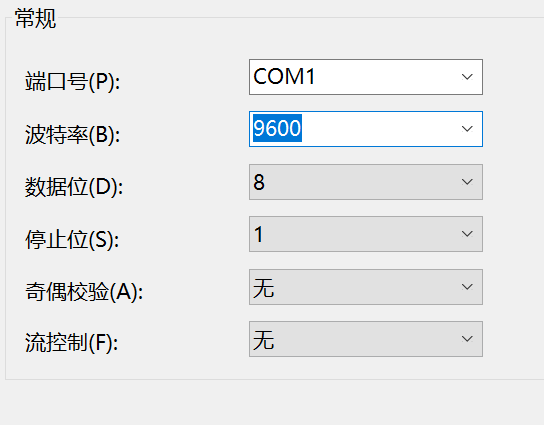
- console方式:适合没有IP地址的网络设备, 通过console线缆与PC的com口相连,通过超级终端软件登录设备, 以命令行的方式实现配置。最常见的方式,使用console方式配置时,COM口的属性要与网络设备的属性向匹配。COM口的数据速率为9600b/s 。
- telnet方式:适合有IP地址的网络设备,并确保PC与网络设备的连通性。
- Web方式:适合有IP地址的网络设备,并内置有WEB页面。
COM口设置:
内存:
- ROM (只读存储器,Read-Only Memory ): 用于存放启动程序。操作系统的引导程序。
- Flash (快闪存储器,Flash Memory ):用于存放操作系统。
- RAM(随机存储器,Random Access Memory): 可读可写的随机存储器,掉电数据消失,存放设备运行过程中产生的数据。
- NVRAM(非易失性随机存储器,Non-Volatile Random Access Memory):断电后仍能保持数据的一种RAM。用于存放启动配置文件( saved-configuration )。
指示灯提示判断:
- 灯灭:代表对应功能未启用。
- 绿色常亮:代表对应功能正常运行。
- 红色常亮:代表报警或出现故障。
常见指示灯:
PWR电源灯:绿色常亮代表正常。
SYS系统运行状态灯:
灭:系统未运行。
常绿:正常运行(慢闪);升级(快闪)。
红色:不正常(常亮);出错(闪烁)。
ETH以太网接口灯:
灭:接口无连接。
常亮(绿):有连接。
闪烁(绿):传输数据。
STCK(stack模式状态灯):
- 灭:未选择stack模式。
- 常亮(绿):指示stack信息。
配置文件:
运行配置文件: 当前配置文件,已保存或尚未保存的文件。
current-configuration (华为)
running-config (思科)
2
启动配置文件: 执行保存命令后的启动配置文件。
saved-configuration (华为)
startup-config (思科)
2
保存当前配置到启动配置命令:
save (华为)
write (思科)
2
# 15.2. 网络设备基本配置命令(华为)
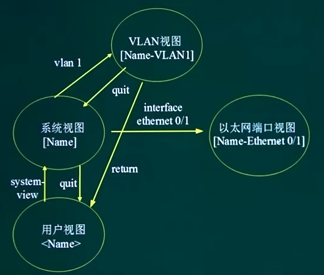
| 视图 | 功能 | 提示符 | 进入命令 | 退出命令 |
|---|---|---|---|---|
| 用户视图 | 查看交换机的简单运行状态和统计信息 | 默认视图 | quit | |
| 系统视图 | 配置系统参数 | [Huawei] | system-view | quit或者return返回用户视图 |
| 以太网端口视图 | 配置以太网端口参数 | [Huawei-Ethernet0/0/1] | 在系统视图下输入 interface Ethernet0/0/1 | quit或者return返回用户视图 |
| Vlan视图 | 配置Vlan参数 | [Huawei-vlan1] | 在系统视图下输入 vlan 1 | quit或者return返回用户视图 |
| Vlan接口视图 | 配置Vlan接口参数 | [Huawei-Vlanif10] | 在系统视图下输入 interface Vlanif 10 | quit或者return返回用户视图 |
| Vty用户界面视图 | 配置单个或多个vty用户界面参数 | [Huawei-ui-vty1][Huawei-ui-vty1-3] | 在系统视图下输入 user-interface vty 1或者 user-interface vty 1 3 | quit或者return返回用户视图 |
| console用户界面视图 | 配置console用户界面视图 | [Huawei-ui-console0] | 在系统视图下输入 user-interface console 0 | quit或者return返回用户视图 |
| RIP/ospf协议视图 | 配置RIP/ospf路由协议参数 | [Huawei-rip-1][Huawei-ospf-1] | 在系统视图下输入 rip/ospf | quit或者return返回用户视图 |
| 基本/高级ACL视图 | 配置ACL协议控制列表 | [Huawei-acl-basic-2100][Huawei-acl-adv-3000] | 在系统视图下输入 acl 2100|acl 3000 | quit或者return返回用户视图 |
华为设备的用户级别:
| 用户级别 | 命令级别 | 说明 |
|---|---|---|
| 0(参观级) | 0 | 网络诊断类命令(ping、tracert),从本设备访问其他设备命令(telnet)等。 |
| 1(监控级) | 0、1 | 系统维护命令,比如display命令。 |
| 2(配置级) | 0、1、2、 | 业务配置命令 |
| 3~15(管理级)在不改变命令级别的前提下,可以理解为3-15用户权限相同 | 0、1、2、3 | 涉及系统基本运行的命令,故障诊断命令debugging命令,还有部分display命令 current-configuration 和 saved-configuration |
常见display命令汇总:
display current-configuration			# 系统当前配置信息
display saved-configuration			    # 系统保存的配置信息
display arp							    # 查看ARP表
display clock							# 时间信息
display logbuffer						# 用户日志信息
display memory-usage					# 内存使用信息
display cpu-usage						# CPU使用情况
display trapbuffer						# 查看告警信息
display version						    # 版本信息
display device						    # 设备信息
display interfaces						# 查看接口信息
display interface brief				    # 查看接口状态和配置的简要信息
display users							# 查看所有通过用户界面登录过的用户
display interface eth-trunk			    # 查看eth-trunk子接口状态
display vlan							# 查看vlan
display stp							    # 查看stp的状态和统计信息
display time-range all					# 查看当前时间段的配置和状态
display gvrp statistics				    # 查看各trunk端口的gvrp统计信息
display acl all						    # 查看所有ACL的配置
display ip routing-table				# 查看路由表
display bfd session all					# 查看所有的BFD会话
display rip 							# 查看所有或指定的RIP进程
display rip route						# 查看RIP路由
display rip neighbor					# 查看RIP的邻居
display ospf lsdb						# 查看OSPF的链路状态数据库信息
display ospf peer						# 查看各OSPF的邻居
display ospf routing					# 查看各OSPF路由
display bgp peer						# 查看BGP对等体
display bgp routing table 				# 查看bgp路由表
2
3
4
5
6
7
8
9
10
11
12
13
14
15
16
17
18
19
20
21
22
23
24
25
26
27
28
29
# 15.2.1. 配置端口IP
二层口是无法直接配置IP的,可以把它加入某个vlan,给这个vlanif口配置IP。三层物理口才能直接配置IP。
CLI粘贴:
system-view
sysname R1
vlan batch 100
interface Vlanif 100
ip address 192.168.1.1 255.255.255.0
quit
interface GigabitEthernet0/0/1
port link-type access
port default vlan 100
return
save
system-view
interface GigabitEthernet0/0/1
ip address 192.168.1.24 255.255.255.0
quit
2
3
4
5
6
7
8
9
10
11
12
13
14
15
实际操作:
# 15.2.2. 启用telnet并配置vty线路登录
实际操作:
<Huawei>system-view												# 进入系统视图
Enter system view, return user view with Ctrl+Z.
[Huawei]telnet server enable									# 使能(开启)telnet服务功能
Info: The Telnet server has been enabled.
[Huawei]user-interface vty 0 4									# 开启vty线路模式,同时允许5个用户登录(0~4)
[Huawei-ui-vty0-4]protocol inbound telnet						# 配置vty入方向开启telnet协议
[Huawei-ui-vty0-4]authentication-mode aaa						# 设置认证模式,有 aaa,password,none三种模式,aaa组合认证,password密码认证,none不需要认证
[Huawei-ui-vty0-4]quit
[Huawei]aaa														# 进入aaa视图
[Huawei-aaa]local-user user1 password cipher Huawei12#$			# 设置用户名为user1,密码为Huawei12#$,ensp可能缺少命令,所以
Info: Add a new user.
[Huawei-aaa]local-user user1 privilege level 3					# 设置账号的权限为3
[Huawei-aaa]return
<Huawei>save													# 进入用户视图,保存
2
3
4
5
6
7
8
9
10
11
12
13
14
CLI粘贴:
system-view
telnet server enable
user-interface vty 0 4
protocol inbound telnet
authentication-mode aaa
quit
aaa
local-user user1 password cipher Huawei12#$
local-user user1 privilege level 3
return
save
2
3
4
5
6
7
8
9
10
11
# 15.2.3. 配置console用户验证
实际操作:
<Huawei>system-view													# 进入系统视图
Enter system view, return user view with Ctrl+Z.
[Huawei]user-interface console 0									# 进入console配置
[Huawei-ui-console0]authentication-mode password					# 设置认证方式为password
[Huawei-ui-console0]set authentication password cipher Huawei12#$	# 设置密码为Huawei12#$,cipher方式密码以密文存储,simple方式密码以明文存储
[Huawei-ui-console0]return
<Huawei>save
2
3
4
5
6
7
CLI粘贴:
system-view
user-interface console 0
authentication-mode password
set authentication password cipher Huawei12#$
return
save
2
3
4
5
6
# 15.3. 华为交换机设备配置
# 15.3.1. 配置端口隔离功能
可实现本台交换机的两个接口之间的二层数据的隔离,而三层数据互通。
实际操作:
[Huawei]port-isolate mode l2								# 配置全局端口隔离模式为二级隔离
[Huawei]interface GigabitEthernet 0/0/1
[Huawei-GigabitEthernet0/0/1]port-isolate enable group 1	# 使能端口隔离模式,并将端口加入group 1
[Huawei-GigabitEthernet0/0/1]quit
[Huawei]interface GigabitEthernet 0/0/2
[Huawei-GigabitEthernet0/0/2]port-isolate enable group 1
[Huawei-GigabitEthernet0/0/2]return
<Huawei>save
2
3
4
5
6
7
8
CLI粘贴:
port-isolate mode l2
interface GigabitEthernet 0/0/1
port-isolate enable group 1
quit
interface GigabitEthernet 0/0/2
port-isolate enable group 1
return
save
2
3
4
5
6
7
8
# 15.3.2. VLAN配置
常见vlan命令汇总:
创建VLAN
[undo] vlan vlan-id										# 删除/创建vlan-id
vlan batch [vlan-id1 to vlan-id2]						# 批量创建VLAN
port link-type [access|trunk|hybrid]					# 配置端口类型
port default vlan vlan-id								# 把端口加入到一个指定VLAN
port trunk allow-pass vlan [vlan-id1 to vlan-id2|all]	# 配置trunk中允许通过的VLAN
port hybrid [tagged|untagged] vlan vlan-id				# 指定hybrid端口以tagged/untagged方式加入VLAN
# 配置管理IP地址和子网掩码
interface vlanif 1
ip address 192.168.0.1 255.255.255.0
2
3
4
5
6
7
8
9
10
实例说明(基于端口划分VLAN):
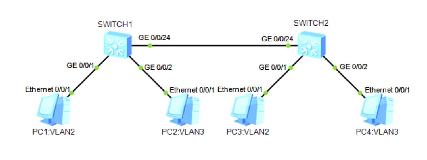
- PC1 和PC3 同属于—个VLAN 2且能相互通信。
- PC2 和PC4 同属于另—个VLAN 3且能相互通信。
- PC 端用户端口类型为access,交换机之间的端口采用带标签的 hybrid 类型或 trunk 类型两个方案。
# 方案1
- 配置交换机所连接的PC端口所属VLAN
交换机 SWITCH1 实际操作:
<Huawei>system-view
Enter system view, return user view with Ctrl+Z.
[Huawei]sysname switch1
[switch1]vlan batch 2 3
Info: This operation may take a few seconds. Please wait for a moment...done.
[switch1]interface GigabitEthernet 0/0/1
[switch1-GigabitEthernet0/0/1]port link-type access
[switch1-GigabitEthernet0/0/1]port default vlan 2
[switch1-GigabitEthernet0/0/1]quit
[switch1]interface GigabitEthernet 0/0/2
[switch1-GigabitEthernet0/0/2]port link-type access
[switch1-GigabitEthernet0/0/2]port default vlan 3
[switch1-GigabitEthernet0/0/2]quit
2
3
4
5
6
7
8
9
10
11
12
13
CLI粘贴:
system-view
sysname switch1
vlan batch 2 3
interface GigabitEthernet 0/0/1
port link-type access
port default vlan 2
quit
interface GigabitEthernet 0/0/2
port link-type access
port default vlan 3
quit
2
3
4
5
6
7
8
9
10
11
交换机 SWITCH2 实际操作同 SWITCH1 类似。
- 配置交换机SW1和SW2连接的端口类型为Hybrid, 井以tagged带标签方式加入VLAN2和VLAN3。
交换机 SWITCH1 实际操作:
[switch1]interface GigabitEthernet 0/0/24
[switch1-GigabitEthernet0/0/24]port link-type hybrid			# 更改端口类型为hybrid
[switch1-GigabitEthernet0/0/24]port hybrid tagged vlan 2 to 3	# 允许vlan2和3通过此端口
[switch1-GigabitEthernet0/0/24]quit
2
3
4
CLI粘贴:
system-view
interface GigabitEthernet 0/0/24
port link-type hybrid
port hybrid tagged vlan 2 to 3
quit
2
3
4
5
交换机 SWITCH2 实际操作同 SWITCH1 相同。
# 方案2
- 交换机配置同方案1。
- 配置交换机SW1和SW2连接的端口类型为trunk,同时允许所有vlan通过。
交换机 SWITCH1 实际操作:
CLI粘贴:
system-view
interface GigabitEthernet 0/0/24
port link-type trunk
port trunk allow-pass vlan all
quit
2
3
4
5
# 补充:基于 MAC 地址划分 VLAN 的实现
实际操作:
[switch1]vlan 3
[switch1-vlan3]mac-vlan mac-address 5489-9897-3A2C			# 需要注意格式,如MAC地址为54-89-98-97-3A-2C,需要改写成5489-9897-3A2C
[switch1-vlan3]quit
[switch1]interface GigabitEthernet 0/0/1
[switch1-GigabitEthernet0/0/1]mac-vlan enable				# 接口视图下使能mac地址划分vlan功能
[switch1-GigabitEthernet0/0/1]quit
2
3
4
5
6
CLI粘贴:
system-view
vlan 3
mac-vlan mac-address 5489-9897-3A2C
quit
interface GigabitEthernet 0/0/1
mac-vlan enable
quit
2
3
4
5
6
7
# 15.3.3. GVRP配置
GARP(Generic Attribute Registration Protocol)是—种通用属性注册协议,包括 GVRP 和 GMRP 两种应用,其中 GVRP 就类似于思科的 VTP 协议。
注册模式:
- Normal 模式:允许动态VLAN在端口上注册。同时发送动态和静态VLAN的声明信息。
- Fixed 模式:不允许动态VLAN在端口上注册。只发送静态VLAN的声明信息。
- Forbidden 模式:不允许动态VLAN在端口上注册。只发送VLAN 1的声明信息。
GVRP 配置案例:实现在交换机SW1和SW2之间通过GVRP功能实现VLAN的动态注册,并达到互通的目的。
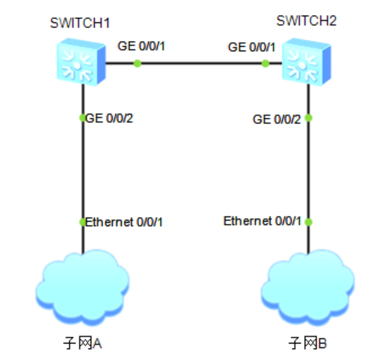
交换机 SWITCH1 实际操作:
<Huawei>system-view
Enter system view, return user view with Ctrl+Z.
[Huawei]sysname switch1
[switch1]vlan batch 2 3
Info: This operation may take a few seconds. Please wait for a moment...done.
[switch1]gvrp														# 全局开启gvrp
[switch1]interface GigabitEthernet 0/0/1
[switch1-GigabitEthernet0/0/1]port link-type trunk
[switch1-GigabitEthernet0/0/1]port trunk allow-pass vlan all
[switch1-GigabitEthernet0/0/1]gvrp 									# 使能端口的gvrp功能
[switch1-GigabitEthernet0/0/1]gvrp registration normal				# gvrp注册模式注册成normal
[switch1-GigabitEthernet0/0/1]quit
[switch1-GigabitEthernet0/0/1]display gvrp statistics				# 查看gvrp的统计信息
2
3
4
5
6
7
8
9
10
11
12
13
CLI粘贴:
system-view
sysname switch1
vlan batch 2 3
gvrp
interface GigabitEthernet 0/0/1
port link-type trunk
port trunk allow-pass vlan all
gvrp
gvrp registration normal
quit
2
3
4
5
6
7
8
9
10
交换机 SWITCH2 实际操作同 SWITCH1 类似,配置 SWITCH2 端口gvrp功能即可。
# 15.3.4. STP配置
# STP配置(需要补充)
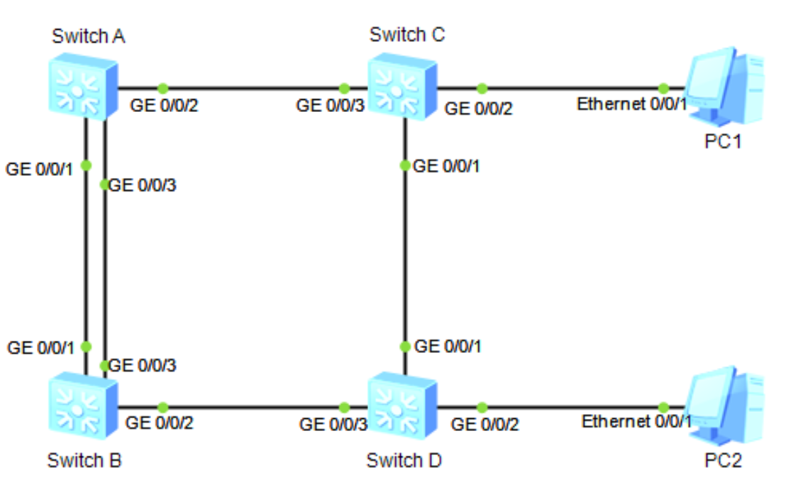
STP配置案例:网络中的交换机 A/B/C/D 均运行生成树协议,来消除网络中的环路。
# RSTP配置(需要补充)
# MSTP配置(需要补充)
# 15.3.5. 链路聚合
将多条物理链路捆绑成一条逻辑链路,实现负载均衡、提高带宽容错(当一条链路失效时,使用其他链路进行通信)。
以太网通道最多可以捆绑8条物理链路,其中物理链路可以是双绞线,也可以是光纤连接。
以太网通道捆绑规则:
- 参加捆绑的端口属于同一个VLAN。
- 如果端口配置的是中继模式,那么应该在链路两端将通道中的所有端口配置成相同的中继模式。
- 所有参与捆绑的端口的物理参数设置必须相同。应该有同样的速度和半双工或者全双工配置。
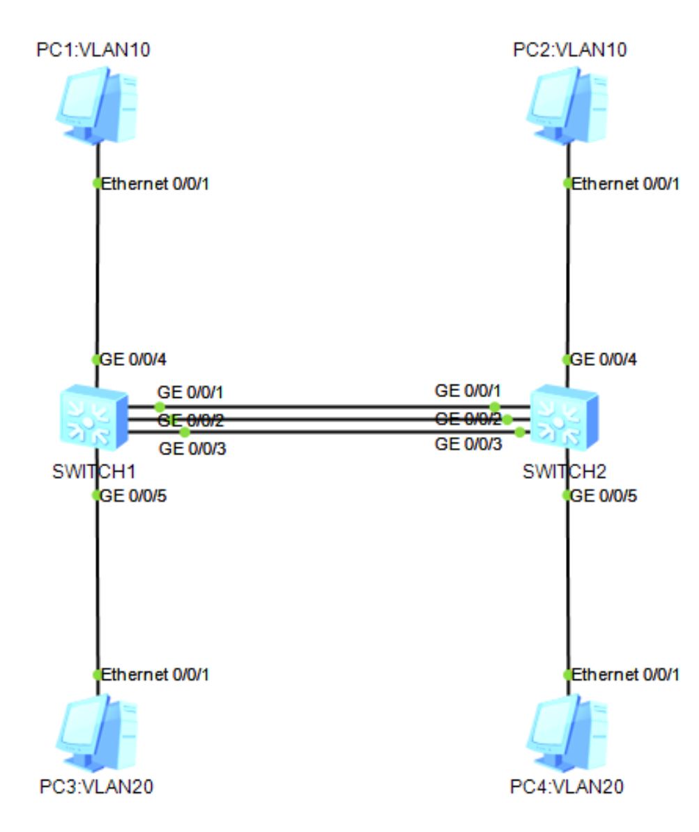
链路聚合配置案例:
# 步骤一:在 SWITCH1 和 SWITCH2 上创建Eth-Trunk接口井加入成员接口
交换机 SWITCH1 实际操作:
<Huawei>system-view
Enter system view, return user view with Ctrl+Z.
[Huawei]sysname switch1
[switch1]interface Eth-Trunk 1											# 创建 Eth-Trunk 链路
[switch1-Eth-Trunk1]trunkport GigabitEthernet 0/0/1 to 0/0/3			# 把端口加入 Eth-Trunk 链路
Info: This operation may take a few seconds. Please wait for a moment...done.
[switch1-Eth-Trunk1]quit
Oct 26 2022 15:59:05-08:00 switch1 %%01IFNET/4/IF_STATE(l)[0]:Interface Eth-Trun
k1 has turned into UP state.
2
3
4
5
6
7
8
9
CLI粘贴:
system-view
sysname switch1
interface Eth-Trunk 1
trunkport GigabitEthernet 0/0/1 to 0/0/3
quit
2
3
4
5
交换机 SWITCH2 实际操作同 SWITCH1 类似。
# 步骤二:创建VLAN井将接口加入VLAN
创建 vlan10 和 vlan20 并分别加入接口:
交换机 SWITCH1 实际操作:
[switch1]vlan batch 10 20
Info: This operation may take a few seconds. Please wait for a moment...done.
[switch1]interface GigabitEthernet 0/0/4
[switch1-GigabitEthernet0/0/4]port link-type access
[switch1-GigabitEthernet0/0/4]port trunk allow-pass vlan 10
[switch1-GigabitEthernet0/0/4]quit
[switch1]interface GigabitEthernet 0/0/5
[switch1-GigabitEthernet0/0/5]port link-type access
[switch1-GigabitEthernet0/0/5]port trunk allow-pass vlan 20
[switch1-GigabitEthernet0/0/5]quit
2
3
4
5
6
7
8
9
10
CLI粘贴:
vlan batch 10 20
interface GigabitEthernet 0/0/4
port link-type access
port trunk allow-pass vlan 10
quit
interface GigabitEthernet 0/0/5
port link-type access
port trunk allow-pass vlan 20
quit
2
3
4
5
6
7
8
9
交换机 SWITCH2 实际操作同 SWITCH1 相同。
配置 Eth-Trunk1 接口允许vlan10 和 vlan20 通过:
交换机 SWITCH1 实际操作:
[switch1]interface Eth-Trunk 1
[switch1-Eth-Trunk1]port link-type trunk
[switch1-Eth-Trunk1]port trunk allow-pass vlan 10 20
[switch1-Eth-Trunk1]quit
2
3
4
CLI粘贴:
interface Eth-Trunk 1
port link-type trunk
port trunk allow-pass vlan 10 20
quit
2
3
4
交换机 SWITCH2 实际操作同 SWITCH1 相同。
# 步骤三:配置 Eth-Trunk1 的负载分担方式
交换机 SWITCH1 实际操作:
[switch1]interface Eth-Trunk 1
[switch1-Eth-Trunk1]load-balance src-dst-mac		# 负载方式为 源地址-目的地址-mac地址
[switch1-Eth-Trunk1]quit
2
3
CLI粘贴:
interface Eth-Trunk 1
load-balance src-dst-mac
quit
2
3
交换机 SWITCH2 实际操作同 SWITCH1 相同。
# 步骤四:验证配置结果
在任意视图下执行 display Eth-Trunk 1 命令, 检查 Eth-Trunk 是否创建成功,及成员接口是否正确加入。
